Connected Components


Next: Feature Metrics Design
Up: Concept Exploration Dataset
Previous: Concept Exploration Observations
Since the characteristics selected as important are geometric in
nature, the Connected Components Data (CC) [1] of the image
will be used as the basic data element instead of the image
pixels. The rationale is that the same degree of information can be
obtained from the CC information as from the image data itself, but
with a great gain in simplicity and performance.
The basic concepts behind the construction of the CC data are the
following:
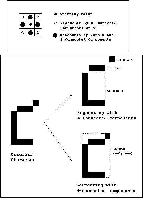
- An 8-connected component is a set of neighboring pixels
of the same color such that any pixel in the set can be reached from
any other pixel in the set by only passing through pixels contained in
the set. The eight possible directions (N, S, W, E, NE, SE, SW, NW)
can be used to travel within the set. Figure 3.7 shows the
difference between 8-connected and 4-connected components.


Figure 3.7: Connected Components
- A connected component box, also known as the minimum
bounding rectangle, is the smallest rectangle that completely encloses
an 8-connected component. Figure 3.7 exemplifies this
concept.


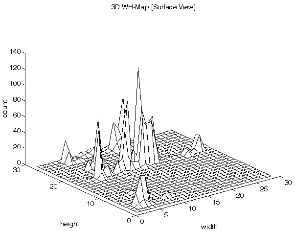
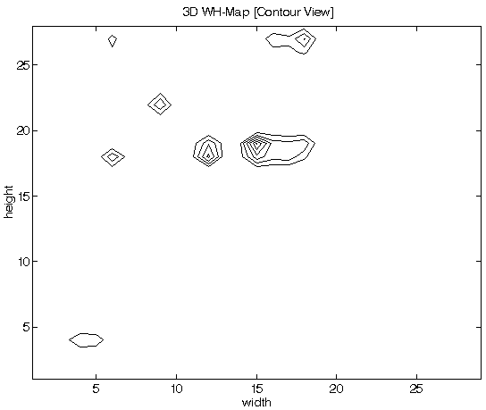
Figure 3.7: Width-Height Map (histogram and closed-contours views)
- A connected components file is the collection of the
starting position (x,y coordinates) and the size (width and height)
information for each and all of the connected components in an image
or part of an image.
- A Width-Height Map (WH-Map) is a 3D frequency
distribution of the contents of a connected components file with the
CC box width and height as the axis. Figure 3.8 shows the
3D histogram and Figure 3.9 shows a closed contour
representation of the WH-Map for a typical image.